1. Conventional hydropower concept
When constructing hydropower plants, the requirements of the European Water Framework Directive (WFD, e.g. ecological prohibition of deterioration) and the Water Resources Act (WRA, e.g. protection of the fish population) must be observed. The construction of new run- of-river power plants is therefore largely limited to existing transverse structures. In the conventional technology, the design follows usually the so-called bays power plant configuration. The turbine flow is diverted from the riverbed into a bay to the power plant and returned to the river, downstream of the damming structure.
Characteristics
- Necessary structural intervention in the river banks
- No conclusive fish protection and fish migration technique
- Outlet with dead water zones in the weir area
- Noise emissions
- Visible powerhouse building is undesirable from an urban planning point of view
- Ecological deterioration ban according to the EU Water Framework Directive
2. New concept Shaft Power Plant (Configuration)
The basic concept of the “Shaft Power Plant” aims to arrange the entire turbine generator unit directly in a “concrete-box” i.e. shaft or in shafts, in order to avoid a classic intake and return with all structural and ecological disadvantages (Fig. 2). As a result, the system requires only a small building volume and has particular ecological advantages, because in the hydraulic design a convincing fish protection and fish descent could be integrated. With the help of a physical model and a prototype system, all components of the building were dimensioned and the system technology developed at the Obernach Research Institute of the TUM.

Advantages of the new concept
- No intervention in the river bank areas
- Conclusive fish protection technique
- Sediment continuity
- Safety in case of flood events
- No disturbances in the landscape (underwaterstructure,nonoiseemission
- Cost-efficient (low construction volume, no need of a power house building)
3. Function
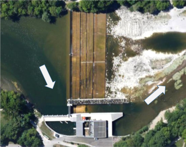
The developed solution involves a plant, which features a fully submerged power plant in front of a weir. The water does not flow through a vertical inlet plane, like in a conventional power plant, but rather through a horizontal inlet plane, parallel to the river bed. The power plant inflow, which discharge is dependent from the water head, is fed to the submersible turbine through the horizontally arranged trash rack and is led via the draft tube through the weir body into the tailwater.


4. Operating Technology
In order to ensure a low-loss and vortex-free flow inlet in the vertical direction are a large inlet plane, fine trash rack, and a permanent flow over the sluice gate required. With the different operational modes of positioning the sluice gate; e.g. gate elevation for rake cleaning and full lowering in case of flood discharge for driftwood and sediment removal, all operational functions are covered (Fig. 4). The fine gravel particles fall into the shaft and are easily flushed into the tailwater via the turbine, coarse bedload is transported with the flow via the rack and with the cleaning device of the trash rack.
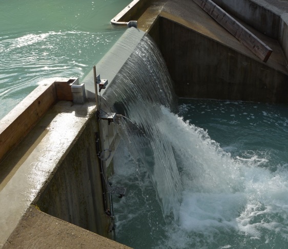


5. Fish protection
Because migratory fish predominantly follow the waterway (mainstream), the hydraulic inlet criteria must be in line with the fish protection and the downstream migratory movement: In the Shaft Power Plant, small bar clearance in the trash rack exerts a barrier effect. Low flow velocities over the inlet area (trash rack) ensure freedom of movement for the fish and the waterjet through and over the sluice gate generates a direct waterway into the tailwater. The
fishes above the inlet plane are tilted (Figure 5 left) and actively swim against the downward flow, allowing the descent paths to be found.


6. Multi-Shaft Concept
In order to have a high degree of expansion at weir sites with larger discharges, an arrangement of in-line individual shafts can be made. The special hydraulic engineering element consists of a so-called “ecological connecting channel” (eco-migration channel), which is connected upstream between the shaft blocks and can be adapted in dimension and structure to the site conditions. As a result, an accessible and easy-to-find waterway with multiple paths is integrated into the reservoir area and the barrier effect of the weir is overcome. Ideally, a close-to-nature design is possible.

